Also known as an ammeter this is one of the instruments that has largely been replaced with an idiot light. Honda Turn Signal Wiring Diagram.
 Automotive Relays 12v 30 40 Amp 5 Pin Spdt Designed Basic Electrical Wiring Automotive Repair Repair
The ECU technical manual TM5-4120-384-14 covered the wiring diagrams and information outlining the differences between the 3-phase and single-phase models.

Amp gauge wiring diagram tsc. The amp gauge. Use 18- to 14-gauge wire for speakers 16- to 12-gauge wire for subs. Any new items added to your cart as Pickup In Store will be sent to the new store.
2004 Verona Transmission Component Diagram. Download SN20 Wiring Diagram. The ammeter should read negative when cranking with the starter then the needle will point in the positive when the tractor is running presuming the charging system is charging.
Reconnect the battery ground cable. Chevy Traverse Wiring Diagram Coil. International Ignition Switch Wiring Diagram.
Best to use a minimum of 12 gauge wires. Easy Installing of a Car Volt Amp Gauge. Connect ammeter lamp 60-0-60-I only to existing instrument panel lighting circuit.
1993 S10 Fuel Pump Wiring Diagram. The RED stoplight wire must be connected to the cold side of the brake pedal stoplight switch. So I guess the small black wire is the common ground and then the small yellow wire is the voltage probe.
If ammeter shows a positive charge when starter is engaged reverse connections on back of ammeter. Download SN10K LS Engine Tach Signal Pull-Up Resistor Wiring Diagram 4815. If the needle on the gauge points opposite reverse the connections on the posts of the gauge.
Get a 4-gauge amp wiring kit- the proper fuse will be included. When you connect to the amp gauge youll use 1 red wire and 1 black wire that will both carry a current. Download SN34 Installation Guide.
SN33 Deluxe Fuel Sender. Volt Amp Meter DROK AC 500V 200A Digital Voltmeter Ammeter Panel 039 Inches LED 2in1 Multimeter 2-Wire Voltage Amperage Tester Gauge with Current Transformer 46 out of 5 stars 157 Misc. The volt gauge will use 1 hot red wire and 1 green grounding wire.
Changing your store affects your localized pricing and pickup locations to new items added to cart. Crimp a round wire terminal onto the end of the black negative wire - coming from your amp gauge. Position your newly crimped wire terminal between the vehicle body and the alternator mount.
Amp Gauge Wiring Diagram Tsc. Give us a call and an Advisor will help you get all the right accessories for your setup. Download SN33 Installation Guide.
Any items already in your cart may change price. The BLACK wire is the power supply line to the brake control. Connect BLACK wire through an automatic reset circuit breaker 20 amp for 1-2 axles 30 amp for 3-4 axles to the POSITIVE terminal of the battery.
Leave the wires loose inside your vehicle while youre working so you dont break or damage them before you finish your installation. Amp Gauge Wiring 1 Always disconnect the ground lead from the vehicle battery before wiring any gauge. Is the least efficient diagram among the electrical wiring diagram.
SN46 Gear Selector. Car Auto Wiring Diagrams. Download SN11 Low Volt Light Wiring Diagram 71212.
A wiring diagram is a simplified traditional photographic representation of an electric circuit. 2 Classic Instruments Amp gauge should only be used on vehicles with alternators rated at 60 Amps or less. TM5-4120-384-24P covered the parts.
You can use speaker wire to male RCA adapters. Ford E 350. Converting a 3-phase model to single-phase would be a daunting task requiring the addition of large capacitors and relays and extensive re-wiring.
Fluorescent Light Wiring Diagram For Ballast. The 002 amp reading with nothing is connected means I might have to use the amps trimmer pot on the accessible back side of the circuit board to zero it but maybe thats just a bit of unconnected amp wires floating in the air effect. Remove the alternator mounting bolt with an appropriately-sized socket wrench and separate the alternator from the vehicles body about 14 inch.
Wire To Throttle Stop Controller To Throttle Stop Controller Air Line Supply Needle Valve. OUTPUT 12 V TRIGGER GROUND THROTTLE STOP CONTROLLER TSC-2A SINGLE CONTROLLER Transbrake Solenoid 12V -AUX Optional Indicator Light THROTTLE STOP CARB STUD 10 Ga. SN34 Fuel Link Module.
Shop for Trailer Wiring Electrical at Tractor Supply. SN11 Low Volt Light. Without it you will not know there is a problem until it is too late.
It reveals the elements of the circuit as simplified forms and the power and signal connections between the devices. 2000 Expedition Fuse Box Diagram. Install an amp gauge in your car and you will instantly know the general condition of your vehicles electrical system.
Using an alternator with higher output capacity is dangerous and could cause a fire. Use 10 gauge wire for Electric Solenoids 18 gauge for CO2 systems. Amp Gauge Wiring Diagram Tsc It is far more helpful as a reference guide if anyone wants to know about the homes electrical system.
Its components are shown by the pictorial to be easily identifiable. Assortment of volt amp meter wiring diagram.
 Gy 0234 12 Volt Amp Gauge Wiring Diagram Free Diagram
 Diagram 9n 12 Volt Wiring Diagram Full Version Hd Quality Wiring Diagram Diagramrt Hosteria87 It
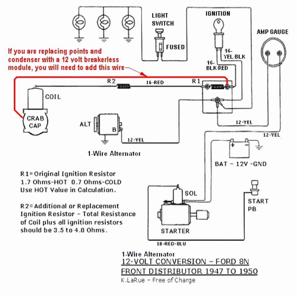 Diagram Diesel Tractor Wiring Diagram Full Version Hd Quality Wiring Diagram Diagramnixg Seagullsully It
 Amp Gauge Wiring Diagram Tsc 79 Cj7 Ignition Wiring Diagram Air Bag Nescafe Jeanjaures37 Fr
Tractor Amp Meter Wiring Diagram Wiring Diagram Diode Total Diode Total Hoteloctavia It


